Dienstag, 12. Juli 2016

DIY 3D Printed DJI OSMO Stand and Accessoires

Finally I pulled the trigger and ordered a DJI OSMO 3 axis stabilized cam system.

In my opinion the OSMO is a very nice cam system for about 600$. Firstly I thought i will just use my Gopro Hero and buy a stabilised axis system for it. But I'm glad I didn't! The quality of this system is just outstanding and the integration of the cam within the axis system is just perfect.

The battery lifetime could be better but that is not a big issue for me (I just ordered a second battery for it, after reading about this problem)

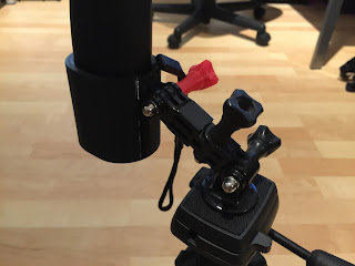
One thing that i really missed is the standard tripod screw on the bottom of the handle. When the OSMO is running and I want to place it somewhere it is really difficult, because I don't want to lay it flat down when the motors are running... So i just designed a few different mounts for the different applications.

DJI OSMO Foldable Stand:

http://www.thingiverse.com/thing:1669017


DJI OSMO Manfrotto Tripod adapter mount:


DJI OSMO Gopro Compatible mount:


All this mounts are designed by myself with Inventor. You can download the files on thingiverse for free and 3D print them at home.

Stanley


Freitag, 8. Juli 2016

3D Systems iSense 3D Scanner for Iphone 6 Plus unboxing and first scan

Today I received my iSense 3D scanner from 3D Systems.


I tried several things with my Kinect and the Skanect software. The results were not too bad but i wanted something more flexible. The Kinect has to be powered from the power socket all the time so this was like the main reason for this device.

I made a short unboxing video and i downloaded the iSense App from the app store. Here is the unboxing and first scan:


Donnerstag, 7. Juli 2016

The perfect FPV Backpack Dakine Mission Photo 25L

As I had my birthday yesterday, my lovely girlfriend gave me a new Dakine Mission Photo 25L backpack for my FPV gear. I was using an old tactical backpack but it was way too small for all the gear i have. So I was pretty happy with my gift :)


As soon as I had some time for sure I was filling everything I had inside the new backpack. And I was surprised all my FPV gear fitted in very well.

The design is well thought and the 25 liters of volume (that is what 25L stands for) are just about the perfect size for the average FPV racer.

Find my complete overview here:


Pocket C.H.I.P. Unboxing

Today my PocketCHIP arrived! Wohoo 😊


I baked the kickstarter campaign and ordered a PockedCHIP. I really liked the idea of having one Raspberry Pi like pocket PC with integrated keyboard, display and battery.

The CHIP itself is a single board computer running a lighter version of a linux distribution. It has a USB port and an audio jack. The micro USB is used to power it up or charge the battery. One charge should last about 4-5h of computing. There are several GPIO ports where you can connect led's, sensors and so on. The PocketCHIP is open source and the developers want you to hack this thing ;-)

As i don't have any plans how to use this thing right now i just made a unboxing video of it... 


Have a good one!


Freitag, 1. Juli 2016

DIY Pool Noodle FPV Racing Gates

DIY Pool Noodle FPV Racing Gates

As i started flying FPV more often with my friend, we soon wanted some more demanding race tracks. In the cool FPV race videos on youtube they use this racing gates from different companies.


I searched the web for a few nice FPV racing gates, but after reading a few reviews from the quality of different gates I was not sure if i'm ready to spend 40-130 CHF for just one gate...


So i just thought i could make some by myself using the well known and cheaply available pool noodle =)


1. I bought 6 pool noodles for 5 CHF a piece.


2. I searched in the craftsmen shop for a plastic pipe in the right dimension to connect the pool noodles. Unfortunately I could not find something that was in the right dimension. So i just I designed a connector piece to connect two pool noodles together. This will give me a variable height of about 120cm. The second design was a foot piece with 6 holes so i can fix the gate by using some camper nails. As i already own a 3D printer i printed the parts. It was a very long print job, it took about 15h for one set (1 connector and 2 feet)


3. The fit of the connector and the foot part was just right so i could slide the pool noodle in the 3D printed parts.


4. This is the gate standing in my hobby room. Hopefully I can try them this Saturday if they withstand the abuse of real FPV racing =)


5. You can download the .stl files from here: http://www.thingiverse.com/thing:1655811

6. The field-test of the gates was with my friend. You can find the movie here: https://youtu.be/Qq9OgPD4Cco 


Graupner MX-20 Hott turning the ring for balancing transmitter

MX-20 transmitter balancer ring hack

I've just ordered a cnc machined rc transmitter balancer. It turned out that the orientation was 90deg off :-) as i liked the cnc finish of the balancer i just thought i could turn the ring.

So here is a step by step tutorial of how you can turn your ring on a Graupner MX-20. As the other Graupner MX transmitters share more or less the design i believe this should also work for an MX-12/16.

1. Open the battery compartment and take out the battery, take out the six screws holding the transmitter together.


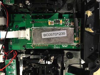
2. Pull the case apart. It should go very easy. Disconnect the antenna and take out the 2 screws holding the antenna module. Flip the antenna module towards the white cable out of the way.


3. Unscrew the 4 tiny screws holding the base board in place. I did this to have a little more room to take out the board under the antenna module i will call this switch board from now.


4. Take out the 4 screws holding the two switches, then unscrew the 2 screws holding the switch board in place.


5. Lift the board a little bit and gently press out the two switches.


6. With the cables connected you cannot take out the switch board completely. But lift it enough so you can loosen the 7mm nut from the ring.


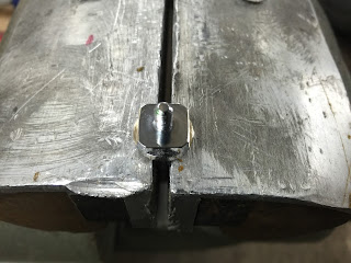
7. Take this ring thing and file a flat surface from about 2mm x 8mm 90 deg from the other flat surfaces.


8. Check the distance of the two surfaces. This should be about 11.5mm.


9. Check the fitment in the transmitter it should be a tight fit, otherwise it could have some play.


10. Once you are happy with the fitment you can assemble the transmitter back together. The procedure is just vice versa. Make sure you don't forget the antenna plug. Now you can mount your transmitter balancer to the transmitter.


Samstag, 25. Juni 2016

Firmware for PTZ 2 Axis brushless gimbal controller

Not so simple brushless controller =)

I got an PTZ 2 axis brushless gimbal from gearbest.com for a review.

http://www.gearbest.com/rc-parts/pp_110479.html


I tried to upgrade to the latest basecam bgc firmware but after my trials the board was not working anymore. And i could not connect to the GUI.

This is a step by step tutorial of how i flashed the original clone firmware back onto the board.

1. Download the hacked "null.hex" file for chinese clone boards from here:
http://www.brokking.net/documents/SimpleBGC_2_2_b2_null.zip

You will need an avr programmer like the usbtinyisp or an arduino. I've used my usbtinyisp for this.


2. Download and install the avrdude software:

Restart your computer.

3. Open the command line tool with cmd


Enter avrdude and press enter, you should see this:


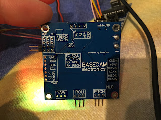
4. Then connect your brushless controller board to your usbtinyisp.


The connectors are pretty self explanatory.


5. Go to the commad line tool and enter:

avrdude -c usbtiny -p atmega328p


When the connection is ok you should see this:


6. Now enter this in avrdude:


avrdude avrdude.conf -c usbtiny -p atmega328p -e -u -U lock:w:0x3f:m -U efuse:w:0x05:m -U hfuse:w:0xDC:m -U lfuse:w:0xEE:m


You should see this:


7.  Now enter this to the avrdude: Please not that you have to set your own file path where you have stored the hex file!!


avrdude avrdude.conf -c usbtiny -p atmega328p -U flash:w:"C:\your own file path!!!!\simplebgc_2_2_b2_null.hex":i -U lock:w:0x0C:m

This can take a while but after it is finished you should see this:


8. Now you can disconnect the usbtinyisp. Connect the board with the usb cable to your computer. Open the Simple brushless controller GUI 2.2.


If you don't have it, you can download it from here:


http://www.basecamelectronics.com/files/v10/SimpleBGC_GUI_2_2b2.zip


9. Open the GUI and select the right port where you have connected your board. Now you can set your desired settings and PID settings to your gimbal.