Update 24.11.2016:
Fixed the link for Witbox Marlin Firmware
Fixed the links of Heatbed, power expander, thermistor and cork insulation.
Added the bulldog clips for reference
If you find any dead link please write a comment so I can fix it ;-)
As i get many emails how I've upgraded my BQ Witbox with the heated bed, I wrote this short tutorial to help you guys out.
There is the possibility to either go with 12V or 24V. I've tried it first with 12V but the heating was way too slow. It took 20mins to reach 50°C. With the 24V power supply it takes roughly 4mins...
Therefore i will describe the upgrade with the 24V power supply.
The less Amps your power supply can deliver, the less temperature you get.
Example: 24V * 6.5A = 156W = 50 - 65°C (Values from Francisco and Damiano)
Losen the four screws on the right side of your Witbox and take the side panel with the plexi of your Witbox away. (The small box is a fan controller)


On the "power in" terminals you can connect your cables going to your 24V power supply. The cable from the 2pin connector will go to the Ramps terminals D8 + and -, either you can use a connector like I did or just solder the wires on the 2pin connector. (I recommend the 2pin connector)

6. 24V power supply.
Connect the wall plug to one side of your cable, the other side is going to the 110V/230V terminals on your 24V power supply. Alternative you can also connect the wall plug side directly to your Witbox power supply 230V terminals. That is the more suitable solution, because with the power switch of the Witbox you can switch everything (Witbox and external 24V power supply) off.
Don't forget the earth connection! Don't connect the wall plug yet!

Connect the other side of your cable coming from the power expander to the 24V + and - terminals of the 24V power supply. You can connect the earth wire on the earth terminal both on the 24V power supply and the 12V power supply inside your Witbox.

The hardware part is nearly finished. I wouldn't close the covers until everything is tested. So let's proceed with the programming.
7. Arduino & configuration.h

On line 160 change the #define BED_MAXTEMP to 100 (just for security) you can change it to a higher value if needed once everything runs good.
Go to line 317 and change #define Z_MAX_POS to 195 this is the printers new max height in Z axis.

If you are loading Firmware 1.4 the variable fan speed implementation is not working. In fact the fan not running with the new Firmware. To make it work again you have to unselect the following parameter.
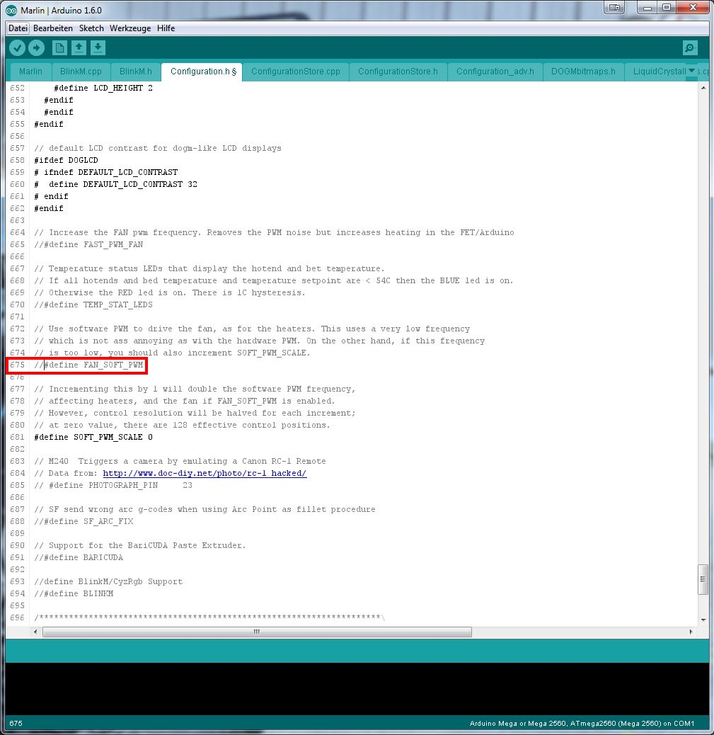
Go to line 675 and unselect #define FAN_SOFT_PWM by placing // in front of the #

Upload the sketch to your Arduino board by pressing the upload button. After the upload is completed you can disconnect your Arduino from your PC.
8. Get everything running
Connect your printer and power supply to power.
Check if the display is running and if there is the new temperature value on the right side next to the extruder temperature. It should indicate your room temperature. If this is not the case, the firmware configuration was not successful.
Check the external power supply on both 110 US / 230 EU and 24V side with your voltage tester.
Check the input and output terminals of your power expander. On the input side you must have 24V and on the output side 0V!
Check the temperature of your heatbed.
It shouldn't be hot by now! If it is hot, disconnect your external power supply from power source. Otherwise your heated bed can get very hot and is not controlled by the Witbox!
Open your favourite slicing software, and go to the machine settings (maybe they are called preferences or something like this) Change your maximum travel in Z axis from 200 to 195mm. Change the configuration/apply the tick on heatbed ON.
Load an easy part, slice it and throw it on the SD card. I recommend to set the heatbed temp to 30°C just to check if it is heating correctly.
Put the SD card in your printer and start the print...
Check if there is power on the output terminals of the power expander. If yes, your heatbed control is working.
Check if the heatbed gets warm. If yes your heatbed connection and power supply is also working.
Now you can just wait until the temperature of the extruder and heatbed reaches it's values and then the print will begin as normal.
Normally for 30°C bed temperature it should take about the same amount of time as for the extruder.
I hope this step by step guide was helpful.
Cheers
Stanley
The less Amps your power supply can deliver, the less temperature you get.
Example: 24V * 6.5A = 156W = 50 - 65°C (Values from Francisco and Damiano)
You will need the following tools:
1. Allen keys
2. Screw drivers
3. Soldering iron
4. Cutting pliers
5. USB to printer USB cable for the programming
6. PC or Mac with Arduino 1.6 http://www.arduino.cc/en/Main/Software
1. Allen keys
2. Screw drivers
3. Soldering iron
4. Cutting pliers
5. USB to printer USB cable for the programming
6. PC or Mac with Arduino 1.6 http://www.arduino.cc/en/Main/Software
You need the following parts:
1. Reprap Heatet bed 200x300 http://www.reprap.me/pcb300.html
2. Reprap Power expander http://www.reprap.me/power-expander.html
3. 100K thermistor http://www.reprap.me/thermistor-smd-1206.html
4. Reprap cork insulation 200x300 http://www.reprap.me/heatbed-thermal-insulator-300.html
5. 1m 0.5-1mm2x2 Cable or wires
6. 3m 1.5mm2x3 Cable or wires
7. 24VDC 5A - 20A power supply
8. Cable ties
9. Z axis sensor spacer http://www.thingiverse.com/thing:802273
9. Optional: Cable chain http://www.thingiverse.com/thing:618799
10. 4 bulldog clips http://www.reprap.me/bulldog-clips.html
Warning! Always disconnect the power from either your Witbox or the 24V power supply when you work on it! It could hurt or kill you!
Let's get started:
Make sure you have printed the Z axis spacer before you proceed!
1. Take your Witbox apart.
Make sure you have printed the Z axis spacer before you proceed!
1. Take your Witbox apart.
Losen the screws from the power supply cover inside your Witbox and remove the cover. You need to unplug the two wires from the fans.
2. Solder the heatbed.
Take your Heatbed and the SMC thermistor. Solder the thermistor to the pads. The direction of the poles doesn't really matter.
Solder the 0.5-1mm2 wires to the pads for the thermistor cables.
At the end take your 1.5mm2 wires and place them to the + and - pads for the power. Make sure they are as flat as possible. Otherwise your heatbed will not be level and you cannot use the whole surface.
Connect the thermistor to the terminal T1 on the Ramps.

3. Place your heatbed inside the Witbox.
Warning! Don't start your printer after you put the new heatbed on your glass plate! The height is different and the extruder will crash in your heatbed!
Place the new heatbed on your glass place. Between the glass and heatbed insert the cork insulation mat. Make sure the cables are long enough so the printing plate can move fully upwards without pulling on the cables. The cables can just hang around or you can print a cablechain like I did.
http://www.thingiverse.com/thing:618799

4. Install your Z axis sensor spacer.
Move your Z axis manually up (take a cloth and turn it by hand. Don't touch it directly with your hands otherwise the spindle will rust) so you can install the Z axis sensor spacer. I've put a little of super glue on mine and it is holding up perfect.
Warning! Don't move your Z axis in automatic mode! The Z axis will crash on the bottom because the distance is now too big!

5. Prepare your power expander.
Take your Heatbed and the SMC thermistor. Solder the thermistor to the pads. The direction of the poles doesn't really matter.
Solder the 0.5-1mm2 wires to the pads for the thermistor cables.
At the end take your 1.5mm2 wires and place them to the + and - pads for the power. Make sure they are as flat as possible. Otherwise your heatbed will not be level and you cannot use the whole surface.
Connect the thermistor to the terminal T1 on the Ramps.
3. Place your heatbed inside the Witbox.
Warning! Don't start your printer after you put the new heatbed on your glass plate! The height is different and the extruder will crash in your heatbed!
Place the new heatbed on your glass place. Between the glass and heatbed insert the cork insulation mat. Make sure the cables are long enough so the printing plate can move fully upwards without pulling on the cables. The cables can just hang around or you can print a cablechain like I did.
http://www.thingiverse.com/thing:618799
4. Install your Z axis sensor spacer.
Move your Z axis manually up (take a cloth and turn it by hand. Don't touch it directly with your hands otherwise the spindle will rust) so you can install the Z axis sensor spacer. I've put a little of super glue on mine and it is holding up perfect.
Warning! Don't move your Z axis in automatic mode! The Z axis will crash on the bottom because the distance is now too big!
5. Prepare your power expander.
Take your power expander and solder the two screw terminals and the 2pin connector to the pads. On the opposite side solder the jumper on the "normal" pad.

Connect the cables going to your heatbed on the "power out" terminals .On the "power in" terminals you can connect your cables going to your 24V power supply. The cable from the 2pin connector will go to the Ramps terminals D8 + and -, either you can use a connector like I did or just solder the wires on the 2pin connector. (I recommend the 2pin connector)
6. 24V power supply.
Connect the wall plug to one side of your cable, the other side is going to the 110V/230V terminals on your 24V power supply. Alternative you can also connect the wall plug side directly to your Witbox power supply 230V terminals. That is the more suitable solution, because with the power switch of the Witbox you can switch everything (Witbox and external 24V power supply) off.
Don't forget the earth connection! Don't connect the wall plug yet!
Connect the other side of your cable coming from the power expander to the 24V + and - terminals of the 24V power supply. You can connect the earth wire on the earth terminal both on the 24V power supply and the 12V power supply inside your Witbox.
The hardware part is nearly finished. I wouldn't close the covers until everything is tested. So let's proceed with the programming.
7. Arduino & configuration.h
If necessary, install the FDTI serial port driver from here: https://static-bqreaders.s3.amazonaws.com/file/Prusa/Driver_FTDI_modificados.zip
Bq is only supporting the precompiled .hex files (thought everything is open source? guess not!) Well I have saved the Marlin 1.4 Witbox original files and the adapted files with the changes already made for the heatbed. Just open the Marlin_1.4_Witbox_Heatbed.ino in the Arduino IDE and load it to your Arduino Mega.
If you want to do it manually by yourself:
If you want to do it manually by yourself:
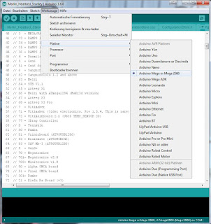
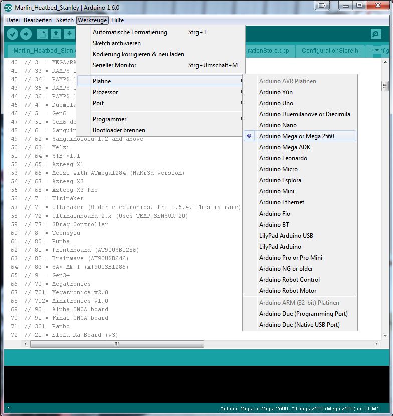
Start the Arduino Software and connect your printer with the USB cable. In the Arduino Software you have too choose the right board and the communication port. Go to "Tools" and select Arduino MEGA 2560, select your com port under "Port"
Open the Firmware "Marlin 1.4 Witbox" and switch to the "configuration.h" tab.
Go to line 135 and change #define TEMP_SENSOR_BED to 1 to define the temperature sensor.
Go to line 135 and change #define TEMP_SENSOR_BED to 1 to define the temperature sensor.

On line 160 change the #define BED_MAXTEMP to 100 (just for security) you can change it to a higher value if needed once everything runs good.
Go to line 317 and change #define Z_MAX_POS to 195 this is the printers new max height in Z axis.

If you are loading Firmware 1.4 the variable fan speed implementation is not working. In fact the fan not running with the new Firmware. To make it work again you have to unselect the following parameter.
Go to line 675 and unselect #define FAN_SOFT_PWM by placing // in front of the #
Upload the sketch to your Arduino board by pressing the upload button. After the upload is completed you can disconnect your Arduino from your PC.
8. Get everything running
Connect your printer and power supply to power.
Check if the display is running and if there is the new temperature value on the right side next to the extruder temperature. It should indicate your room temperature. If this is not the case, the firmware configuration was not successful.
Check the external power supply on both 110 US / 230 EU and 24V side with your voltage tester.
Check the input and output terminals of your power expander. On the input side you must have 24V and on the output side 0V!
Check the temperature of your heatbed.
It shouldn't be hot by now! If it is hot, disconnect your external power supply from power source. Otherwise your heated bed can get very hot and is not controlled by the Witbox!
Open your favourite slicing software, and go to the machine settings (maybe they are called preferences or something like this) Change your maximum travel in Z axis from 200 to 195mm. Change the configuration/apply the tick on heatbed ON.
Load an easy part, slice it and throw it on the SD card. I recommend to set the heatbed temp to 30°C just to check if it is heating correctly.
Put the SD card in your printer and start the print...
Check if there is power on the output terminals of the power expander. If yes, your heatbed control is working.
Check if the heatbed gets warm. If yes your heatbed connection and power supply is also working.
Now you can just wait until the temperature of the extruder and heatbed reaches it's values and then the print will begin as normal.
Normally for 30°C bed temperature it should take about the same amount of time as for the extruder.
I hope this step by step guide was helpful.
Cheers
Stanley