Update 24.11.2016:
Fixed the link for Witbox Marlin Firmware
Fixed the links of Heatbed, power expander, thermistor and cork insulation.
Added the bulldog clips for reference
If you find any dead link please write a comment so I can fix it ;-)
As i get many emails how I've upgraded my BQ Witbox with the heated bed, I wrote this short tutorial to help you guys out.
There is the possibility to either go with 12V or 24V. I've tried it first with 12V but the heating was way too slow. It took 20mins to reach 50°C. With the 24V power supply it takes roughly 4mins...
Therefore i will describe the upgrade with the 24V power supply.
The less Amps your power supply can deliver, the less temperature you get.
Example: 24V * 6.5A = 156W = 50 - 65°C (Values from Francisco and Damiano)
Losen the four screws on the right side of your Witbox and take the side panel with the plexi of your Witbox away. (The small box is a fan controller)


On the "power in" terminals you can connect your cables going to your 24V power supply. The cable from the 2pin connector will go to the Ramps terminals D8 + and -, either you can use a connector like I did or just solder the wires on the 2pin connector. (I recommend the 2pin connector)

6. 24V power supply.
Connect the wall plug to one side of your cable, the other side is going to the 110V/230V terminals on your 24V power supply. Alternative you can also connect the wall plug side directly to your Witbox power supply 230V terminals. That is the more suitable solution, because with the power switch of the Witbox you can switch everything (Witbox and external 24V power supply) off.
Don't forget the earth connection! Don't connect the wall plug yet!

Connect the other side of your cable coming from the power expander to the 24V + and - terminals of the 24V power supply. You can connect the earth wire on the earth terminal both on the 24V power supply and the 12V power supply inside your Witbox.

The hardware part is nearly finished. I wouldn't close the covers until everything is tested. So let's proceed with the programming.
7. Arduino & configuration.h

On line 160 change the #define BED_MAXTEMP to 100 (just for security) you can change it to a higher value if needed once everything runs good.
Go to line 317 and change #define Z_MAX_POS to 195 this is the printers new max height in Z axis.

If you are loading Firmware 1.4 the variable fan speed implementation is not working. In fact the fan not running with the new Firmware. To make it work again you have to unselect the following parameter.
Go to line 675 and unselect #define FAN_SOFT_PWM by placing // in front of the #

Upload the sketch to your Arduino board by pressing the upload button. After the upload is completed you can disconnect your Arduino from your PC.
8. Get everything running
Connect your printer and power supply to power.
Check if the display is running and if there is the new temperature value on the right side next to the extruder temperature. It should indicate your room temperature. If this is not the case, the firmware configuration was not successful.
Check the external power supply on both 110 US / 230 EU and 24V side with your voltage tester.
Check the input and output terminals of your power expander. On the input side you must have 24V and on the output side 0V!
Check the temperature of your heatbed.
It shouldn't be hot by now! If it is hot, disconnect your external power supply from power source. Otherwise your heated bed can get very hot and is not controlled by the Witbox!
Open your favourite slicing software, and go to the machine settings (maybe they are called preferences or something like this) Change your maximum travel in Z axis from 200 to 195mm. Change the configuration/apply the tick on heatbed ON.
Load an easy part, slice it and throw it on the SD card. I recommend to set the heatbed temp to 30°C just to check if it is heating correctly.
Put the SD card in your printer and start the print...
Check if there is power on the output terminals of the power expander. If yes, your heatbed control is working.
Check if the heatbed gets warm. If yes your heatbed connection and power supply is also working.
Now you can just wait until the temperature of the extruder and heatbed reaches it's values and then the print will begin as normal.
Normally for 30°C bed temperature it should take about the same amount of time as for the extruder.
I hope this step by step guide was helpful.
Cheers
Stanley
The less Amps your power supply can deliver, the less temperature you get.
Example: 24V * 6.5A = 156W = 50 - 65°C (Values from Francisco and Damiano)
You will need the following tools:
1. Allen keys
2. Screw drivers
3. Soldering iron
4. Cutting pliers
5. USB to printer USB cable for the programming
6. PC or Mac with Arduino 1.6 http://www.arduino.cc/en/Main/Software
1. Allen keys
2. Screw drivers
3. Soldering iron
4. Cutting pliers
5. USB to printer USB cable for the programming
6. PC or Mac with Arduino 1.6 http://www.arduino.cc/en/Main/Software
You need the following parts:
1. Reprap Heatet bed 200x300 http://www.reprap.me/pcb300.html
2. Reprap Power expander http://www.reprap.me/power-expander.html
3. 100K thermistor http://www.reprap.me/thermistor-smd-1206.html
4. Reprap cork insulation 200x300 http://www.reprap.me/heatbed-thermal-insulator-300.html
5. 1m 0.5-1mm2x2 Cable or wires
6. 3m 1.5mm2x3 Cable or wires
7. 24VDC 5A - 20A power supply
8. Cable ties
9. Z axis sensor spacer http://www.thingiverse.com/thing:802273
9. Optional: Cable chain http://www.thingiverse.com/thing:618799
10. 4 bulldog clips http://www.reprap.me/bulldog-clips.html
Warning! Always disconnect the power from either your Witbox or the 24V power supply when you work on it! It could hurt or kill you!
Let's get started:
Make sure you have printed the Z axis spacer before you proceed!
1. Take your Witbox apart.
Make sure you have printed the Z axis spacer before you proceed!
1. Take your Witbox apart.
Losen the screws from the power supply cover inside your Witbox and remove the cover. You need to unplug the two wires from the fans.
2. Solder the heatbed.
Take your Heatbed and the SMC thermistor. Solder the thermistor to the pads. The direction of the poles doesn't really matter.
Solder the 0.5-1mm2 wires to the pads for the thermistor cables.
At the end take your 1.5mm2 wires and place them to the + and - pads for the power. Make sure they are as flat as possible. Otherwise your heatbed will not be level and you cannot use the whole surface.
Connect the thermistor to the terminal T1 on the Ramps.

3. Place your heatbed inside the Witbox.
Warning! Don't start your printer after you put the new heatbed on your glass plate! The height is different and the extruder will crash in your heatbed!
Place the new heatbed on your glass place. Between the glass and heatbed insert the cork insulation mat. Make sure the cables are long enough so the printing plate can move fully upwards without pulling on the cables. The cables can just hang around or you can print a cablechain like I did.
http://www.thingiverse.com/thing:618799

4. Install your Z axis sensor spacer.
Move your Z axis manually up (take a cloth and turn it by hand. Don't touch it directly with your hands otherwise the spindle will rust) so you can install the Z axis sensor spacer. I've put a little of super glue on mine and it is holding up perfect.
Warning! Don't move your Z axis in automatic mode! The Z axis will crash on the bottom because the distance is now too big!

5. Prepare your power expander.
Take your Heatbed and the SMC thermistor. Solder the thermistor to the pads. The direction of the poles doesn't really matter.
Solder the 0.5-1mm2 wires to the pads for the thermistor cables.
At the end take your 1.5mm2 wires and place them to the + and - pads for the power. Make sure they are as flat as possible. Otherwise your heatbed will not be level and you cannot use the whole surface.
Connect the thermistor to the terminal T1 on the Ramps.
3. Place your heatbed inside the Witbox.
Warning! Don't start your printer after you put the new heatbed on your glass plate! The height is different and the extruder will crash in your heatbed!
Place the new heatbed on your glass place. Between the glass and heatbed insert the cork insulation mat. Make sure the cables are long enough so the printing plate can move fully upwards without pulling on the cables. The cables can just hang around or you can print a cablechain like I did.
http://www.thingiverse.com/thing:618799
4. Install your Z axis sensor spacer.
Move your Z axis manually up (take a cloth and turn it by hand. Don't touch it directly with your hands otherwise the spindle will rust) so you can install the Z axis sensor spacer. I've put a little of super glue on mine and it is holding up perfect.
Warning! Don't move your Z axis in automatic mode! The Z axis will crash on the bottom because the distance is now too big!
5. Prepare your power expander.
Take your power expander and solder the two screw terminals and the 2pin connector to the pads. On the opposite side solder the jumper on the "normal" pad.

Connect the cables going to your heatbed on the "power out" terminals .On the "power in" terminals you can connect your cables going to your 24V power supply. The cable from the 2pin connector will go to the Ramps terminals D8 + and -, either you can use a connector like I did or just solder the wires on the 2pin connector. (I recommend the 2pin connector)
6. 24V power supply.
Connect the wall plug to one side of your cable, the other side is going to the 110V/230V terminals on your 24V power supply. Alternative you can also connect the wall plug side directly to your Witbox power supply 230V terminals. That is the more suitable solution, because with the power switch of the Witbox you can switch everything (Witbox and external 24V power supply) off.
Don't forget the earth connection! Don't connect the wall plug yet!
Connect the other side of your cable coming from the power expander to the 24V + and - terminals of the 24V power supply. You can connect the earth wire on the earth terminal both on the 24V power supply and the 12V power supply inside your Witbox.
The hardware part is nearly finished. I wouldn't close the covers until everything is tested. So let's proceed with the programming.
7. Arduino & configuration.h
If necessary, install the FDTI serial port driver from here: https://static-bqreaders.s3.amazonaws.com/file/Prusa/Driver_FTDI_modificados.zip
Bq is only supporting the precompiled .hex files (thought everything is open source? guess not!) Well I have saved the Marlin 1.4 Witbox original files and the adapted files with the changes already made for the heatbed. Just open the Marlin_1.4_Witbox_Heatbed.ino in the Arduino IDE and load it to your Arduino Mega.
If you want to do it manually by yourself:
If you want to do it manually by yourself:
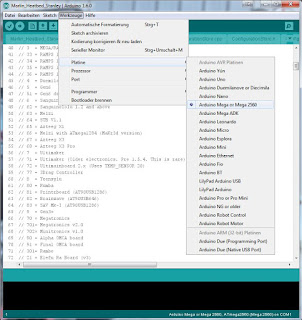
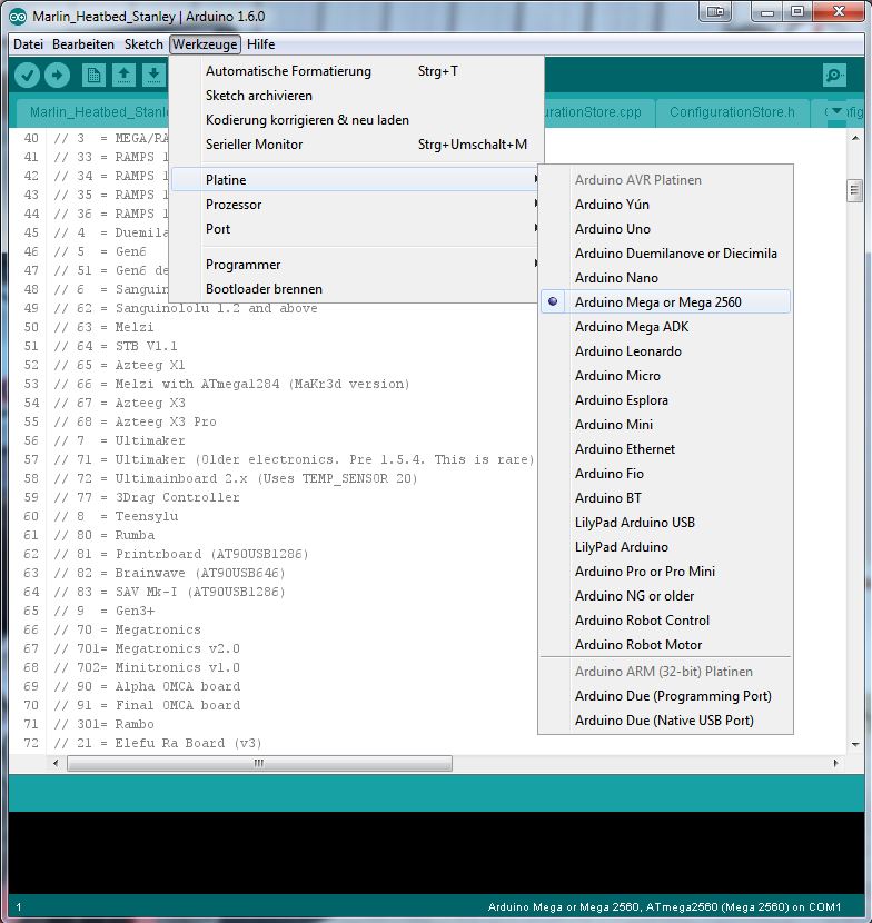
Start the Arduino Software and connect your printer with the USB cable. In the Arduino Software you have too choose the right board and the communication port. Go to "Tools" and select Arduino MEGA 2560, select your com port under "Port"
Open the Firmware "Marlin 1.4 Witbox" and switch to the "configuration.h" tab.
Go to line 135 and change #define TEMP_SENSOR_BED to 1 to define the temperature sensor.
Go to line 135 and change #define TEMP_SENSOR_BED to 1 to define the temperature sensor.

On line 160 change the #define BED_MAXTEMP to 100 (just for security) you can change it to a higher value if needed once everything runs good.
Go to line 317 and change #define Z_MAX_POS to 195 this is the printers new max height in Z axis.

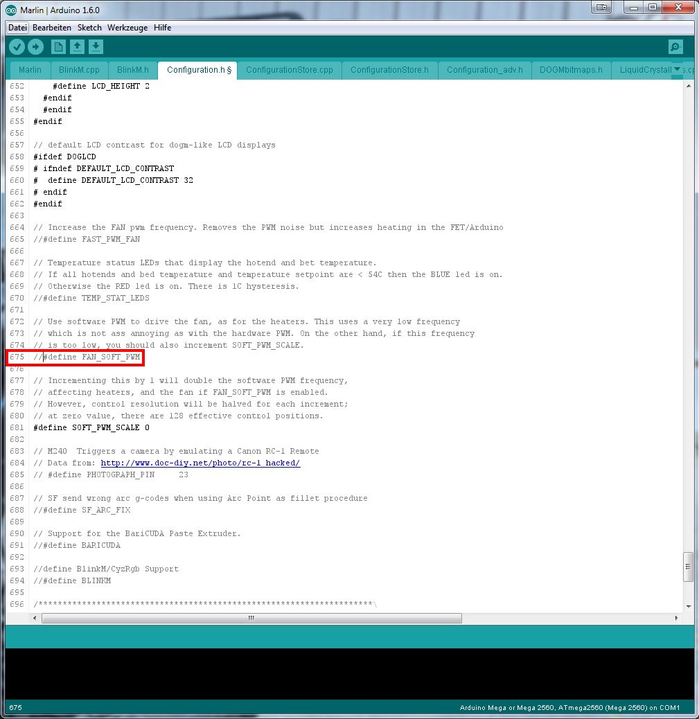
If you are loading Firmware 1.4 the variable fan speed implementation is not working. In fact the fan not running with the new Firmware. To make it work again you have to unselect the following parameter.
Go to line 675 and unselect #define FAN_SOFT_PWM by placing // in front of the #
Upload the sketch to your Arduino board by pressing the upload button. After the upload is completed you can disconnect your Arduino from your PC.
8. Get everything running
Connect your printer and power supply to power.
Check if the display is running and if there is the new temperature value on the right side next to the extruder temperature. It should indicate your room temperature. If this is not the case, the firmware configuration was not successful.
Check the external power supply on both 110 US / 230 EU and 24V side with your voltage tester.
Check the input and output terminals of your power expander. On the input side you must have 24V and on the output side 0V!
Check the temperature of your heatbed.
It shouldn't be hot by now! If it is hot, disconnect your external power supply from power source. Otherwise your heated bed can get very hot and is not controlled by the Witbox!
Open your favourite slicing software, and go to the machine settings (maybe they are called preferences or something like this) Change your maximum travel in Z axis from 200 to 195mm. Change the configuration/apply the tick on heatbed ON.
Load an easy part, slice it and throw it on the SD card. I recommend to set the heatbed temp to 30°C just to check if it is heating correctly.
Put the SD card in your printer and start the print...
Check if there is power on the output terminals of the power expander. If yes, your heatbed control is working.
Check if the heatbed gets warm. If yes your heatbed connection and power supply is also working.
Now you can just wait until the temperature of the extruder and heatbed reaches it's values and then the print will begin as normal.
Normally for 30°C bed temperature it should take about the same amount of time as for the extruder.
I hope this step by step guide was helpful.
Cheers
Stanley
Hi Stanley,
AntwortenLöschenThanks for the detailed instructions. Helped me a lot at the beginning.
Also I have an idea that might simplify/improve this conversion.
The whole extruder assembly is secured on the carriage with two screws. The geometry allows you to place some spacers - or a printed plate with the exact thickness of your headed bed assembly - between the carriage and the extruder assembly. This way you do not have to touch the Z axis endstop, nor to decrease Z-axis movement. When not using the heated bed, just take out the spacers.
Best regards
Miklos
hi!
Löscheni am from hungary.
can you help me??
i have a witbox 2 with some problem...
thank you!
Greycat
greycats@gmail.com
Hey Miklós,
AntwortenLöschenThank you for your good input. I didn't looked at this, but now when you bring on the idea I must say you're completely right :-)
I will change it in the blog as soon as I have time.
Best regards
Stanley
Hello Stanley:
AntwortenLöschenFirst of all thank you for all this job it was so useful to me.
I've been following all the steps to mount the heat bed and it's working fine except for a little problem that I hope you can help me to solve.
Then heatbed is so slow to reach high temperatures, and when it hits 64ºC it stops heating and won't go any further. I'm using a 24V and 6.3A power supply, shouldn't be enough?
I don't know what is the problem here maybe you can give me some hints to improve the speed of heating.
Thanks and best regards.
Kiko
Hey Francisco,
LöschenSorry for my late response, but actually I'm not sure why it is not heating up more than 64C°. Maybe there isn't enought Amps to heat it up further? Could you try another more powerful power supply?
Best regards
Stanley
Hey i don't understand where the thermistor cable goes and where the pin cable from the power expander goes. Can somebody help me please? Maybe also uploading some photos will be great. thank you.
AntwortenLöschenHey Damiano,
LöschenThe thermistor cable goes to the T1 terminal. On your Ramps it seems there is no marking for this terminals. But it doesn't really matter, the hardware layout is for sure the same as the other Ramps. So just connect it on this terminal T1.
https://3.bp.blogspot.com/-it7ZZQ5KH2M/VUKMIMXAN1I/AAAAAAAAALE/ht3MLCekSfc/s1600/RAMPS_top.jpg
Best regards
Stanley
Thank you :)
Löschenoh yes man it works perfectly. I have to find a way to fix better the hot bed but it works, it warms up and perfectly read the temperature.
LöschenThank you soooooooooooo much for your blog and your help!!!
Hey Damiano,
LöschenThat's AWESOME :-) I'm happy that it worked out! No problem!
Best regards
Stanley
i said it too early :( for some reason the bed cannot go up to 53 deg. that's weird because the power supply is 6.5a 150w 24v, so this should be fine. I'll maybe ask to reprap team if they know something.
LöschenHi all. Just to update what i'm doing: I asked to reprap and they said me to use a powerful supply. I bought a 24v 20A and 480W power supply (before i had 24V, 5A and 150W PS), i'm waiting for it and it will take a bit to come. When it comes i'll update the tests :D
LöschenHey Damiano, awesome thank you for the update! :-) I hope it will work.
Löschenit will take around one month to come (i got it on a chinese cheap website) but actually i'm printing stuff at 40° and it prints really great. no more need to use paper-tape and glue it :D and no debris left on the bed. I really love the upgrade!
LöschenSo finally the new power supply is arrived. Badly it has exactly the same behavior of the old one: really really difficult to reach 40 deg and no way to go over 50 deg. So i'm guessing maybe some lines in the code need to be edited and/or maybe something out of my knowledge is happening in the power expander. Totally no idea. My next step will be to bypass the power expander and connect directly the power supply to the heatbed and see if without control it heats up. Stanley do you think it will be safe as a test keeping a hand on the switch off button? :D thanks
Löschenhttps://www.3dee.at/wp-content/uploads/Witbox-Arduino.jpg adn i have this on my machine. i can't find t1.
AntwortenLöschenHello Stanley
AntwortenLöschenIt is really a good work, congratulation
Hop you it's possible to mount a heatbed to the Witbox 2
A big thanks
Best regards
Hello Christophe,
LöschenThank you i really appreciate it :-) Unfortunately i don't have a Witbox 2. I have seen they use a custom made electronics board and not the Ramps 1.4 anymore. So with that in mind I'm not sure if it is that possible to adjust the Firmware like in Arduino IDE. But would need to try it...
Best regards
Stanley
Hello Stanley
AntwortenLöschenIt does not have been a long time since the Witbox 2 went out.
Can be that somebody will find.
It is can be the firmware which will raise problem, I believe that there is a connector for the heatbed on the card.
Best regards
Christophe
PS : Sorry for my bad english Lol
Hello Stanley
AntwortenLöschenOn the card, it's a connector HBP (i think Heatbed)
But i not found the thermistor connector, it's 4 connector for the thermistor
In the firmware, i found :
- #define TEMP_SENSOR_BED 0
- #define BED_MINTEMP 5
- #define BED_MAXTEMP 150
- #define Z_MAX_POS 200
I would like to try, but I am afraid of bungling the firmware.
If I knew also how to or connect the thermistor of the bed
Best regards,
Christophe
Can you post a pic of the card? I bet there are two ports to connect two thermistors. :-D
LöschenRegards
Stanley
Here's all files for Zum CNC ==> https://github.com/bq/zum/archive/master.zip
Löschenhttp://i84.servimg.com/u/f84/12/26/05/41/zum_cn10.png
http://i84.servimg.com/u/f84/12/26/05/41/zum_cn10.jpg
Best regards,
Christophe
When i know if it's possible, i buy all parts.
AntwortenLöschenHello Stanley
AntwortenLöschenNews ==> i have tryed tu compile the firmware with the instruction in the Marlin Folder, I did not make a success.
Or I forgot some thing or I take myself there badly
At the moment, it is not decisive!!
Best regards,
Christophe
Hey Christophe, have you tried this?
AntwortenLöschenhttps://github.com/bq/Marlin/blob/master/Documentation/Windows_Compilation.md
I have not found a compiled .ino file on github
Stanley
Yes, i have tried, he says :
AntwortenLöschen" RMDIR bin/"
" RM .config_mach"
Impossible de trouver C:\Marlin-2.1.0\Marlin\.config_mach
" RM .config_lang"
Impossible de trouver C:\Marlin-2.1.0\Marlin\.config_lang
Configurating for witbox_2 printer...
Language selected: English [EN] \(by default\)
1 fichier(s) copié(s).
1 fichier(s) copié(s).
make: `language/EN' is up to date.
make: *** No rule to make target `bin/wiring.o', needed by `bin/Marlin.elf'. Stop.
make: *** No rule to make target `bin/wiring.o', needed by `bin/Marlin.elf'. Stop.
" RMDIR bin/"
" RM .config_mach"
" RM .config_lang"
Christophe
Hello Stanley
AntwortenLöschenI dont have succes with compile the firmware.
Think that if i buy :
- Arduino Mega 2560
- Ramps 1.4
- Display
- Kit for heated bed
I can have a Heated bed independent from the printer.
I just control the temperature of the heated bed with the display.
It's possible ??
Best regards
Christophe
Hello Stanley
AntwortenLöschenNews about firmware lol
I managed to compile the firmware, but when I change BED_SENSOR on 1, during the compilation, he puts full of errors on the tempreatur.cpp file
Damage
Hey Christophe,
AntwortenLöschenOk good at least you could compile it :-)
What are the errors in the temperature.cpp file?
It's very long
AntwortenLöschenI put the errors in a file txt ==> https://mega.nz/#!El93lQqB!tltdWZsSCCwuC56R_seNCvaFTm390KOQZgCpJ7ee-ZU
Have you see my question for the independant heated bed ?
AntwortenLöschenWhat are you think about this ?
Oh wow the error is big :-) and i have no clue what it means ;-)
AntwortenLöschenYeah you could easily control an independent heated bed...
But have you written an email to the guys from BQ? I'm sure they can help you with it since the electronics card is prepared for it...
Yes, it's very big lol
AntwortenLöschenBq do not want to give of information, I their have already asked
I think that I am going to make an independent heated bed, I think that it will be the simplest solution.
I shall thus have to put a firmware in the arduino, but which?
In any case, a big thank for your answers.
Oh why? They call it Opensource?! So why shouldn't they help you?? I mean at least for the compilation of their firmware...
AntwortenLöschenDo you have a working .ino from this firmware?
It is what I their said, it was open source.
AntwortenLöschenHe told me " We cannot help you, it would cancel the guarantee "
I don't have .ino, when i compil it, i have only the .hex file.
For the independent heated bed, What firmware do I have to take?
hi!
Löschenwhat is with your witbox2 projekt??
the heatbed is work??
i have some problem....
thank you!
Greycat
Hey Christophe, I have an idea of how you could upload your .hex file to your arduino mega. :-) Let me know if you still want to do it. regards Stanley
AntwortenLöschenhey are you able to send me the firmware as the link doesnt work anymore
AntwortenLöschenthank you
mitchell.carli@adelaide.edu.au
Hey Stanley,
AntwortenLöschenfirst of all thanks for this great tutorial :)
Could you please tell me how you fixed your heatbed and the cork mat on the original bed?
Best regards,
Andreas
Hey Andreas,
LöschenHehe thank you :-) I fixed the heatbed and the cork mat with 4 binder clips.
https://en.wikipedia.org/wiki/Binder_clip
I got them from a local papery shop, they had different ones. I bought the smaller ones so I'm not loosing too much space on the printing bed.
Best regards,
Stanley
Ahoi,
Löschensuper, thank you :)
Sorry for my noob questions^^, but could you really print directly on the PCB with some bluetape, or do you have an extra glass plate on it?
Best regards,
Andreas
Hey Andreas, no problem :-)
AntwortenLöschenI print directly on the pcb no bluetape needed. I just use a thin film of 3D Lac.
Best regards
Stanley
thank you :)
LöschenHi Stanley!
AntwortenLöschenGreat job! :)
This upgrade and modified firmware work with witbox2 ???
Thnx!
Greycat
Hello Greycat,
LöschenYes it should also work with the Witbox 2 :-)
Best regards
Stanley
hi!
Löschendon't work!
the bed crushed with printhead... :(
why??
thnx!
Br. Greycat
Hey Greycat.
LöschenHave you downloaded the latest version of Marlin firmware from here: https://github.com/bq/Marlin
You have to change the Z-axis max height! Otherwise your print bed will travel up too far!
#define Z_MAX_POS 200
Best regards
Stanley
Thank you!
LöschenBut this is witbox2...
I have to change z max pos to 160.
But the bed comming up to printhead.
Please look the witbox 2 config file!
What need on file changing?!
Thank you!
Greycat
Hey Greycat,
LöschenI've changed the Configuration.h file for you. I have set the Z axis height to 195! Normally your heated bed should not be taller than 5mm?!
https://workbench.grabcad.com/workbench/projects/gc7yFPsh1MK5h90_mP5YmNuCDtspvCtAcohmTbS2lxP3IS#/space/gcwaGSo0_ycgZaZsSo9nRl0rexV_mRstSRAxKqg4rAsext
Best regards
Stanley
Thank you!
Löscheni test it!
Greycat
Der Kommentar wurde von einem Blog-Administrator entfernt.
AntwortenLöschenDer Kommentar wurde von einem Blog-Administrator entfernt.
AntwortenLöschenHello Stanley,
AntwortenLöschenI've just upgraded my Witbox, following your instructions which I'm very grateful for. My bed also struggles to get above 50 degrees. I have a 24v supply that can deliver 15amps so ample power. However the resistance of the board is 5 ohms and which means the maximum power a 24v supply can produce is 24x24/5=115watts. I then noticed that there is a marking on the back of the printed heat bed which states 140w. I have adjusted the voltage up on my supply to 28.8 volts giving me more power than 140watts and I have carefully insulated the underside of the bed. Looking at other beds on the market (unfortunately not the 200x300 size needed) i see that their resistance is around 1 to 2 ohms which suggests a greater power can be handled. Do you think we are restricted by this 140watt rating or can we safely increase the power by wiring on the 12volt terminals and giving it say 18volts?
Hello Puerlin,
LöschenYes on the RepRap page it says:
Running 24V on a 12V setting will heatup the heatbed to 100 degree Celsius in only 2 minutes (while consuming 443 - 576 Watts!!!)
So if your power supply is strong enough, it should be possible to run it with 24V on the 12V terminals.
Let me know if it worked!
Best regards
Stanley